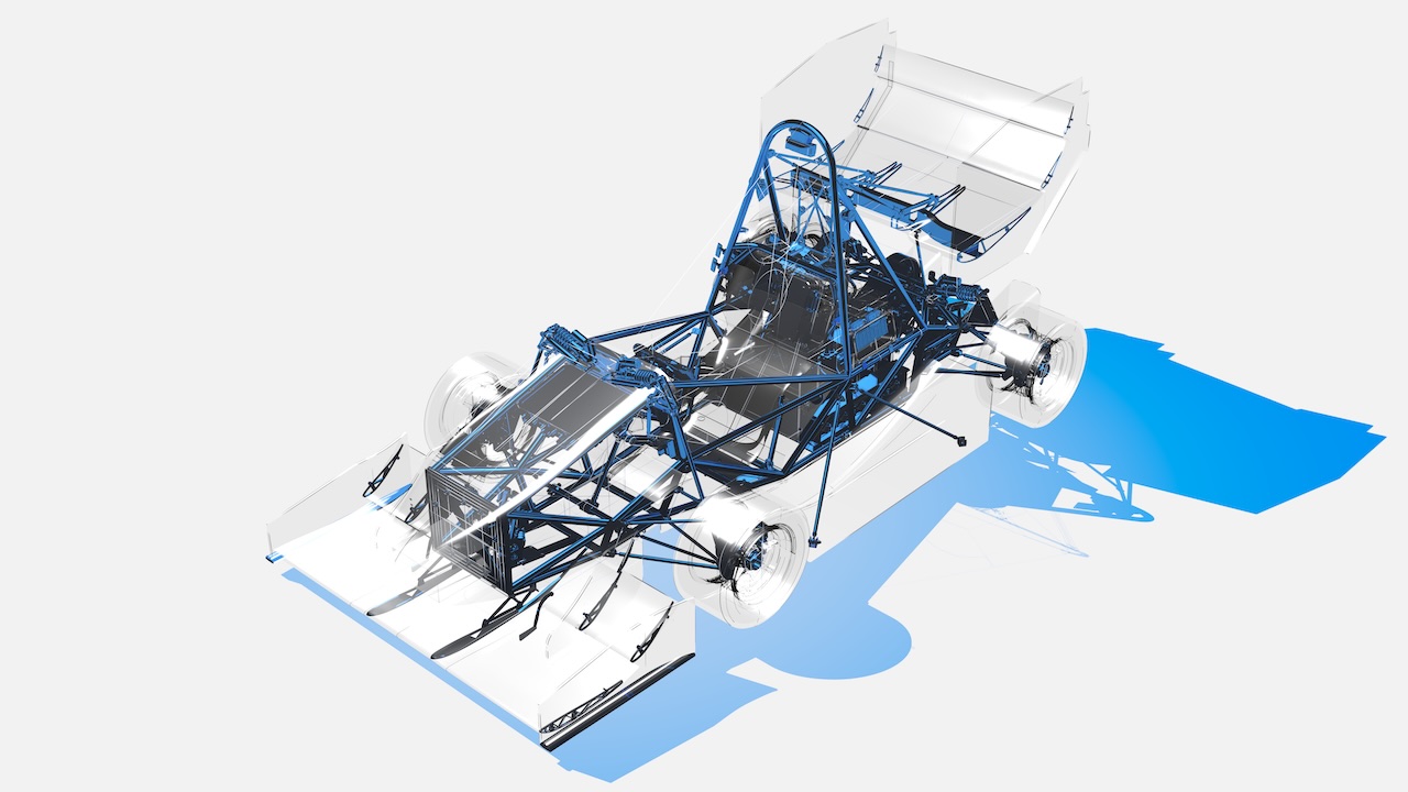
The beauty of draftsmanship is increasingly distant from modern engineering. Being the champion of computer graphics that I am, I decided to solve this problem… with C++ and USD.
Draftsmanship is classic. I previously thought that such effects would best be captured by screen-space image kernels and non-photorealistic shading. While effective, they fail to portray the precision I’m after. Having worked with a handful of CAD tools for robotics, I became curious if there was a better bridge between the visual language of engineering and the tools used for 3D content creation.
The trick is in the geometry.
Those who work with 3D content creation tools are generally familiar with meshes. They are the primary representation used throughout most media pipelines. Engineers, however, generally prefer a parametric representation called B-rep (boundary representation) as the canonical representation of a part. The unmistakable “CAD” look comes from this distinction. For each one of the faces, the boundary is rasterized in screen space as a black line with a constant width.
For engineering applications, these edges aren’t particularly important once the model is converted for simulation or manufacturing, so most tools don’t make much effort to preserve them. In the “high-end” of rendering for VFX and animation, parametric geometry has largely become a legacy feature, with meshes and curves being the dominant representations.
Luckily, B-rep to mesh is a fairly standard operation in engineering. The harder problem is everything around it. CAD models are hierarchical, heavily instanced, and often carry metadata that is useful long after the geometry itself has been converted. If only there were a widely accepted format designed to ferry all of this information into a modern 3D application…
Enter OpenUSD! It is a blah, blah. I don’t need to introduce the benefits of this format. In a CAD context however, the only player in town that works with these files natively is omniverse. It only works with a nvidia-ized system which is less than ideal, and it doesn’t mesh the wireframe or the sketches. I’ve also found that it is flakey and no super undebuggable.
Step To USD
You can view the code here. This is the first serious CLI I’ve written and been forced to use. The goals were as follows:
- Novel geometry. The tool had to embed wireframes (and sketches time permiting), so we can get the classy CAD look.
- Fast and robust. Car assemblies are large and full of warts, so iteration is important. Given the trouble that I had with Omniverse, the iteration loop would have to be tight such that problematic assemblies could be pointpointed quickly. Also, during the look development process, this proved handy for remeshing parts with new parameters.
- Per Prim Overrides The CLI itself is minimal. All of the “options” are applied per prim and reside in a usd schema.
The user will start by writing a usd stage that looks something like:
#usda 1.0
(
    defaultPrim = "WonderfulModel"
    metersPerUnit = 0.001
    upAxis = "Z"
)

def StepTessellationOptions "DefaultOptions" {
    double step:mesh:angularDeflection = 0.1
    double step:mesh:linearDeflection = 0.1
    # other options...
}

def StepContainer "WonderfulModel" {
    asset step:sourceAsset = @../step/model.STEP@
    def StepPrototypes "Prototypes" {
        rel step:defaultParams = </DefaultOptions>
    }
}
The user feeds a CAD file into the CLI, which traverses the stage to find the StepContainer. From there, the tool generates two main prims: {MODEL_PATH}/Assembly and {MODEL_PATH}/Prototypes (MODEL_PATH is /WonderfulModel in this case).
(cg) duck@capote mk11 % stepmesh -h
 stepmesh -- Meshes all StepContainer prims in a Usd scene
 Options:
    -i, --input <path>               Path to the input Usd file.
    -p, --prim  <sdfPath>            Only tessellate the prim...
    -q, --quiet                      Suppress all output.
    -v, --verbose                    Prints like everything.
    -h, --help                       Prints this message.

    usage: stepmesh -i <path> [options]
/Assembly is essentially a shell hierarchy that maintains the heirarchical structure of how the engineers originally authored the model. Leaf Xforms author reference arcs (with instanceable = true) back to the corresponding prototypes. This keeps the USD representation (mostly) renderer friendly and performant by just having a single level instance (see AOUSD forum on hydra instance flattening).
/Prototypes contains a flat list of each unique prototype. Each prototype then contains a sub-prim for each geometry representation we generate: the mesh, wireframe, and any other derived geometry. At a high level, the geometry lives entirely under */Prototypes, while */Assembly only describes how those pieces are arranged.
The prototype generation is then broken up into independent jobs and fed through TBB. Special care is taken to avoid stage recomposition by batching the geometry output writes in huge SdfChangeBlocks. Alongside caching the parsed .step document, MK11 is meshed in right around 90 seconds.
(cg) duck@capote mk11-model % stepmesh -i model-v3.usda
Loading cached XBF from /home/duck/mk11/mk11-model/step/model-v3.xbf
Working OCC length unit: 0.001000 m
Assembly tree built: 8659 nodes
  Assemblies:          2127
  Leaves:              6532
  Unique definitions:  1717
Container prim path: /Mk11
[1717/1717] Writing prototypes  {LOD=low}...
[8659/8659] Writing Assembly...
[1717/1717] Writing prototypes  {LOD=high}...
[8659/8659] Writing Assembly...
[280/3434] Tessellating Geometry...
[ERROR] OCC exception on /Mk11/Prototypes/COMPOUND_1_step_1__98e6574f (def index 1075): Bnd_Box is void
[281/3434] Tessellating Geometry...
[ERROR] OCC exception on /Mk11/Prototypes/COMPOUND_1_step_1__98e6574f (def index 1075): Bnd_Box is void
[WARNING] ShapeFix_Shape for part /Mk11/Prototypes/HV11_PCB_04_Integration_V3_1__665858fc: operation timed out
[1347/3434] Tessellating Geometry...
[ERROR] OCC exception on /Mk11/Prototypes/Part5_AD11_FW_001_FW_TOP_ASSEMBLY_FDR_1__88817cd8 (def index 889): Bnd_Box is void
[1348/3434] Tessellating Geometry...
[ERROR] OCC exception on /Mk11/Prototypes/Part5_AD11_FW_001_FW_TOP_ASSEMBLY_FDR_1__88817cd8 (def index 889): Bnd_Box is void
[3434/3434] Writing geometry...
Total Time Taken: 82.046385 seconds
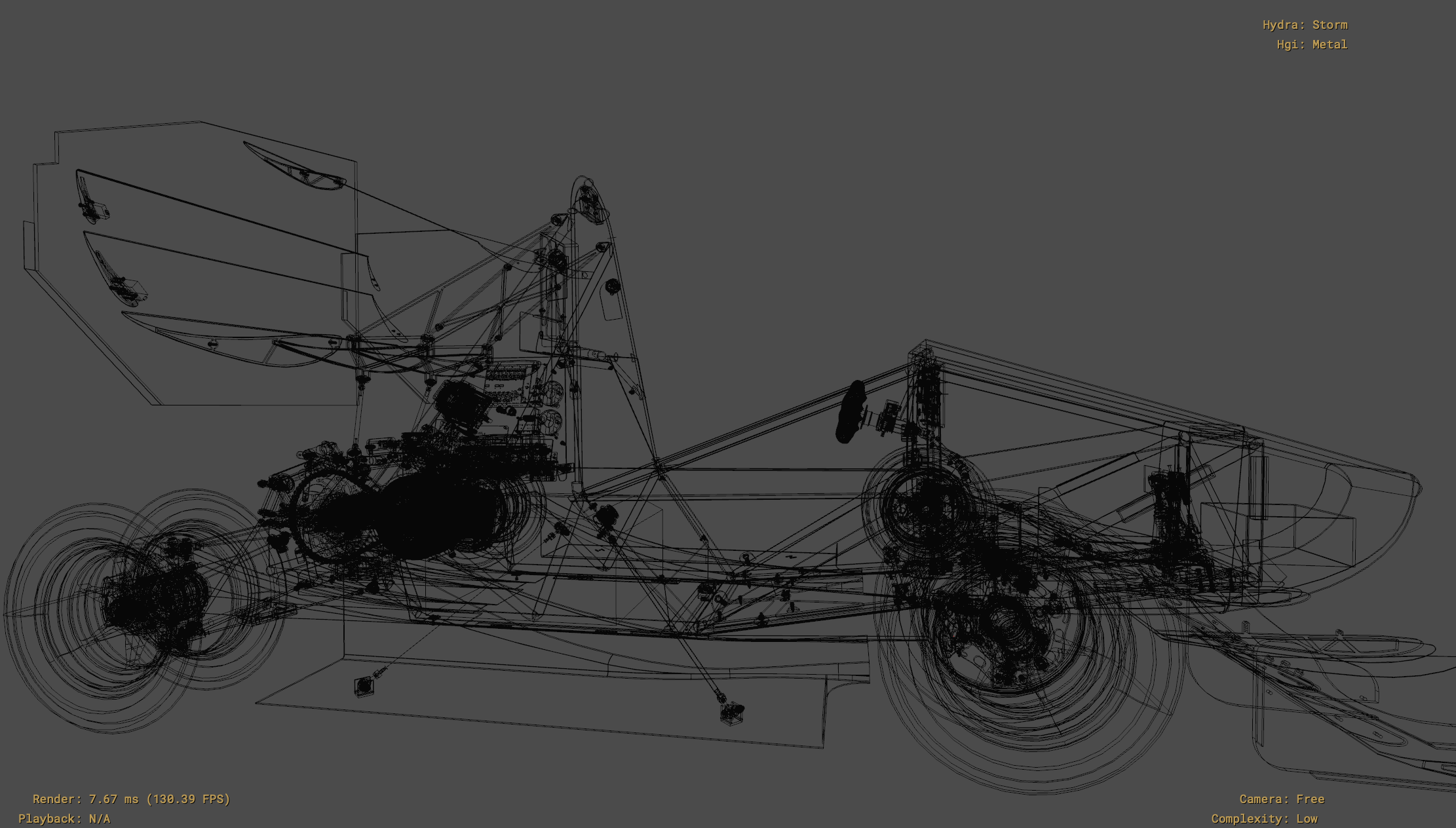
Engineers work like artists from the standpoint of the cleanliness of what they make, so error messages like these are really important. Mk11 had 1717 prototypes in total, all of which had to land in the final model. In one instance, the HV panel, a particularly feature-rich assembly, was resolving as one solid in the STEP document and proving to be troublesome. When I opened the stage, the car took 8 seconds to open. Too many prims? As it turns out, every edge on every surface-mounted electrical component was generating a curve prim with two vertices each, resulting in 200-ish thousand sub-prims for the prototype! Upon finding this out, I added an option to coalesce the curves of a given solid into one prim. After much trial and error, I was tremendously excited to see Mk10 in usdview!
But I had yet to sucessfully shove the car in a production path tracer. When I attempted RenderMan XPU, the generated curves didn’t fit within the new uint16 max vertex limit that RenderMan now expects. I had to change the coalescing to shard up to a user defined limit and alas, the car was rendering.
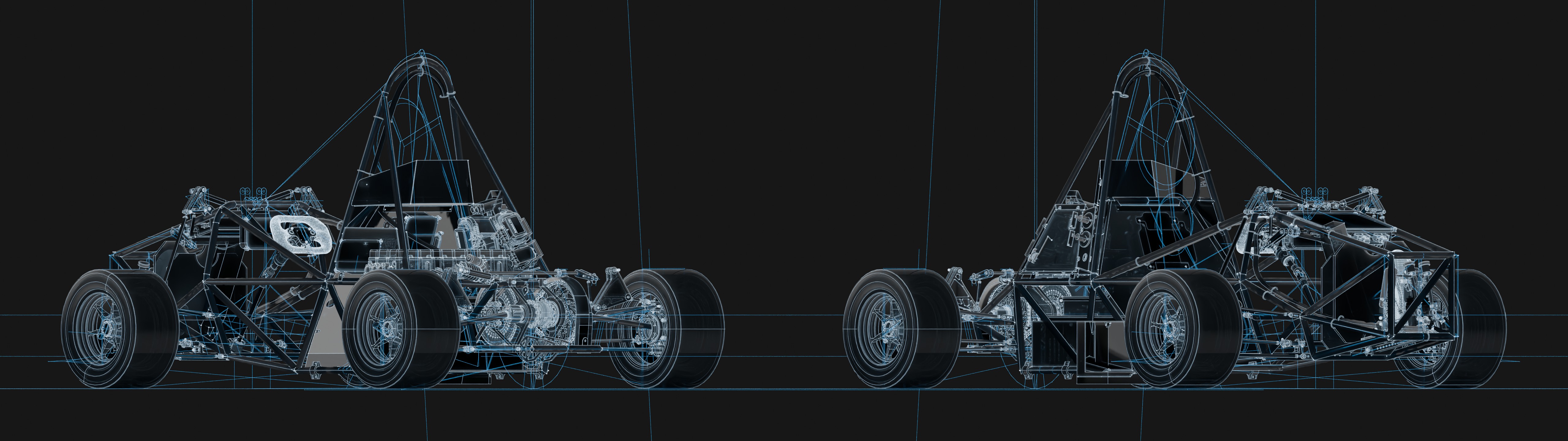
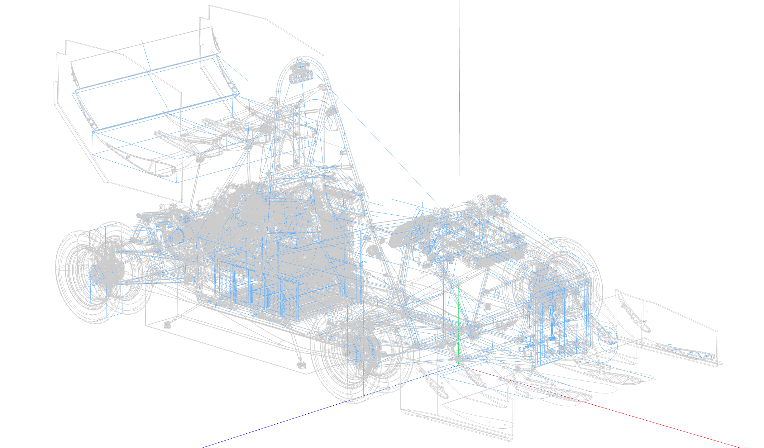
What is up with those lines? Well, initially they appear to asymptotically explode to infinity, so maybe there was a divide-by-zero somewhere? No. The model in Fusion 360 shows the same thing, so this was firmly a SolidWorks export problem. Okay, I should mention something. The tool takes in STEP files, but those aren’t modeled directly by the engineers. They use SolidWorks, which has its own format. I would’ve built the tool around the respresentation directly, but the provided C++ API is closed source and only works on DOS which makes it weird. Since the curves can be optionally split out into multiple prims, I deactivated the problematic curves one by one.
Future Directions
“There is always one more thing to do.”
Top of mind is a better meshing algorithm. Right now the alrogihm used is the default one included with opencascade. In addition to being slow the topology is poor. An alternate meshing scheme could go a long way in reducing potential rendering artifacts and triangle counts. Instant meshes or quadriflow would be a great starting point and are both open source. There is potentially a path towards a ‘BRep guided’ solution where the the smoothness energy and tangent fields are guided by sampling BRep topology instead of relying exclusively on one extracted from the mesh.
There are some others but that is the big one. Stay tuned for part two!